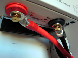
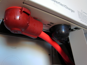
Today we mounted various components and started wiring things together. I’m afraid this will jump around a little. (And please if any one notices me doing anything suspicious, speak up.) First thing today, I connected the thick cables that will bring power from the batteries to the inverter. There is one really large breaker/disconnect between the batteries and where they connect to the inverter here. Note that I still have not connected the batteries to the system.
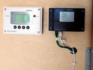
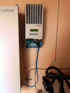
Next I mounted the other of the parts of the system: System Control Panel, Automatic Generator Start, and the Solar Charge Controller. My continuing education made a jump today when I realized why there are two battery chargers in the system. The one in the inverter converts AC from the generator, (or the grid if you have such a thing) the Solar Charge Controller converts DC from the Solar Panel array for battery charging. (It’s smarter than that actually (see MPPT), but basically that is it.)
And, yes that is a giant heat sync built into the SCC.
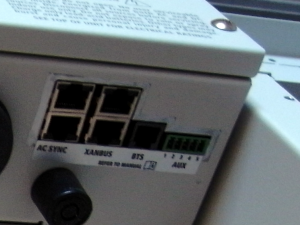
You will see what look like network cables running between the different component. And, indeed they are good old CAT5 network cables. All the devices talk to each other. There’s something a little funky in the system given that each device has two network connectors and the two ends have special terminators. It seems odd to me, but I assume they are doing interesting things. (One thing that I am sure of, is that they are providing power to some of the devices.) Here’s a picture of everything mounted. The installation instructions tell you to run the network cables early because things get crowded later on. I took them at their word and ran the cables as soon as the everything was mounted.
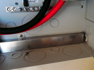
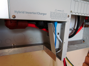
The next three pictures show the paths the network cabling take. Inside the PDP, there are special raceways for the network cabling. This is to shield the cables from interference and to help keep things organized.
You don’t see cabling to the SCP because it’s in the wall. For some reason, the SCP mounting hardware really wants a hole in the wall for the network cable; I obliged.
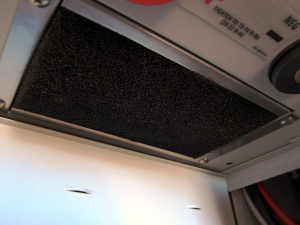
Now that I remember, the very first thing I did was install the air filter in the bottom of the inverter. You just push it in place with your hands.
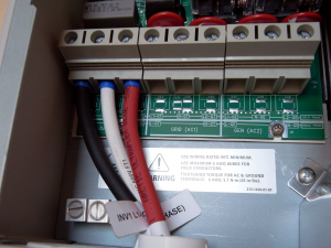
The last thing for today was to connect up the wires that bring AC from the inverter to the breakers from which the house is the next stop.
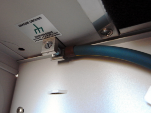
And to ground the inverter.


Looking good dad.
Its a great tutorial, God bless