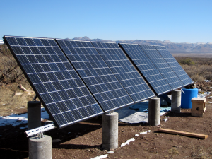
The first row of solar panels is installed. It’s time to look at wiring them together.
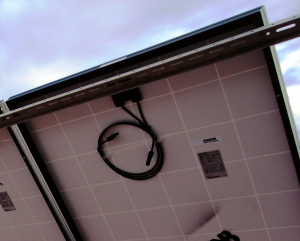
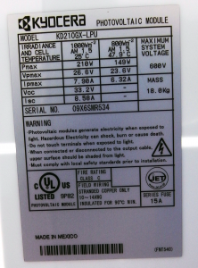
Each solar panel (data sheet, installation manual) has two cables on the back, one with a male connector and the other with a female connector. You can connect solar panels together (in series) with these cables. The more panels you connect together the greater the voltage. Because you need to have circuit breakers between the solar panels and the inverter/battery charger, you need to keep the voltages down to a level that’s reasonable for your DC breaker.
Our breakers can handle up to 150 volts. We will wire in groups of three panels which generates about 100 volts.
After you have connected your panels together, you’re left with one male and one female connector. One of these is positive and one is negative. These need to be connected to the combiner/breaker box. With our purchase, we got four 30 foot cables with the same connectors as the solar panels. What you do, is cut these in half (or so, depending on your arrangement) and use the two pieces to connect the solar panels to the breaker box. The end with the connector attaches to the solar panel, you strip the wire on the other end and hook it up in the combiner box. One very nice thing about this arrangement, is that you can wire the cables to the breaker box before you plug into the solar panel. This is very nice because solar panels can’t be switched off if it’s sunny.
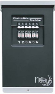
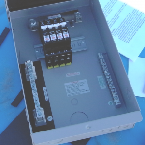
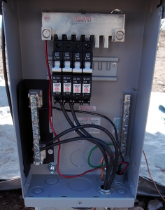
The combiner box we are using is from Midnight Solar. We will use four of the available six spots for circuit breakers. If we ever find that we need to get more solar panels, all we need to do is add some breakers and we’re ready to go.
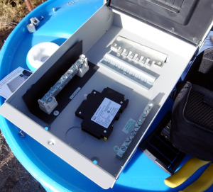
It turns out that this combiner box needs some assembly. That’s because it was designed for a variety of uses. It was pretty simple to figure out what we needed, but it was hard for me to figure out how it fit together.
There is a plate that the breakers fit into that looks like it mounts in the box; it doesn’t. It kind of hangs in the air. The breakers have a screw in the back that clamps down on the plate. Once you get a few breakers installed, it’s quite secure. This plate supplies the combined (in parallel) power of all the solar panels to the battery charger.
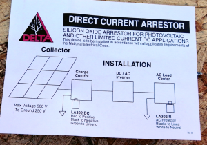
I have a DC lightning arrestor that will be installed in the combiner box. It connects to ground, neutral, and the combined DC output. (We actually have a variety of lightning arrestors that will go throughout the system.) I don’t really know how much protection things like this provide, but considering the lightning I’ve seen here so far, it seems worth trying.
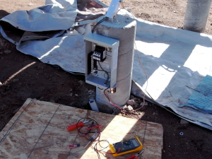
As for grounding the panels and combiner box, I put a grounding rod into the ground (eight feet down) inside of the center back concrete column. Bare copper wire is running from the grounding rod out of the column. I’ll use this to ground all the solar panels and the combiner box. (We had to order special little connectors that attach the grounding wire to each of the solar panels.)
There was a brief hiccup before we actually wired the solar panels to the combiner box. Someone asked a question regarding the rated amps (15 amps) for for the breakers and the amps coming from the solar panels. The case is that when you connect panels in serial, the voltages add and the amps stay the same. (If you combine in parallel, the amps add and the voltage stays the same.) So, the circuit breakers we have are fine.
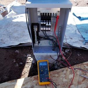
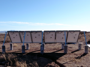
The wiring in pictures…


You didn’t mention if you checked the output with a Fluke (err multimeter). Did you end up with some voltage?
What inverter are you using?
The inverter we’re using is the Xantrex XW 6048.
I may not have said whether or not I saw voltage, but if you look at the voltmeter in the picture, you’ll see 94.1 volts.