It’s been a little while since I worked on the Xantrex (solar) system. Two main things caused the delay. One was that a few items needed to be ordered before I could finish the installation. The other was that we got started with the first coat of stucco and wanted to finish that as quickly as possible.
What needed to be ordered? We needed two DC breakers and one AC breaker. The DC breakers are clearly called for in the wiring diagrams. I wondered why they didn’t just come with the inverter. I can only assume that it’s because there are so many possible ways to configure this system and that some don’t use those breakers. The AC breaker is because I want power in the battery house. Other things I needed were flexible conduit, 3/4 inch and 1/2 inch, adapters for the 1 inch knockouts to 3/4 and 1/2 inch.
The first thing I tackled was the wiring of the solar array to the SCC. I used one of the new DC breakers to do this. The negative wire coming from the solar array goes into the PDP and directly to the PV- spot in the SCC (the white wire at #3 below). The positive wire goes to the top of the new DC breaker (the top of #1 – not visible). A new wire is added from the bottom of this breaker to the PV+ in the SCC (See #1 goes to #3). Note that this was done with the breaker in the OFF position.
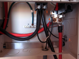
PDP DC wiring
I then ran the wires from the SCC to the battery. These wires allow the SCC to charge the battery bank. The negative wire from the SCC goes to the DC negative busbar in the PDP (See the white wire above #2 below). The positive wire goes to the top second new DC breaker (also in the off position). (See #1 below.) A new wire goes from the bottom of this breaker to the positive DC busbar (See #2 and #4 above) attached to the large DC breaker where the positive cable from the battery attaches.
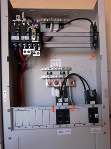
The upper half of the PDP
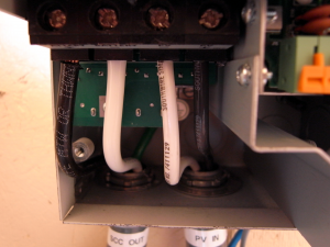
Solar Charge Controller wiring
Next the networking cables needed to be attached and then moved. For whatever reason, I placed the network terminator to the right. When I went to install the cover for the SCC, it would not fit because the terminator blocked the place where the screw attaches. I reversed the cable and the terminator, and all was well.
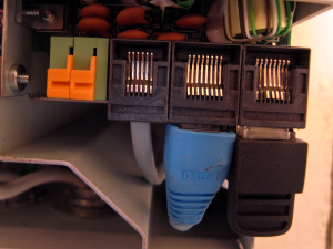
Networking and battery sensor cables
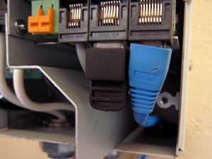
Adjusted so the cover fits
The battery temperature sensor was attached in the SCC as well. Speaking of the battery sensor… I’ve read the manuals quite a bit and was not sure what to do with the two battery sensors I received. Somewhere I read that only one was required; the data is shared on the network. Elsewhere I read that if there is more than one, whichever one has the higher value is used. That made me think that there’s value in using both of them. So I installed both of them. One attaches to the inverter and the other to the SCC. I attached the sensor ends to two different batteries in the battery bank.
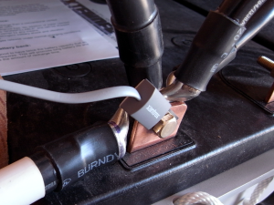
The battery sensor installed
The next thing I did was to hook up the positive cable from the battery bank. The only tricky thing about this is that it made sense to me to connect the cable inside the PDP first and then connect the other end to the battery bank. I was worried about touching the hot end of the cable somewhere inside the PDP it should not touch.
I believe the system is ready to be turned on. I decided to give it a day before doing this. I’ve read over the manuals and think I’m ready. I’ll turn on the system tomorrow.
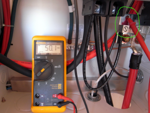
Voltage from the battery bank at the PDP
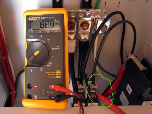
Solar array voltage at the PDP
The order of operations as I see them is to first throw the breaker (#3 below) that connects the battery bank. This should bring up everything except the SCC. There may be a little bit of configuration required at this point. It seems that everything can be done from the System Control Panel. I believe the SCC can be configured at this point, but I’m not positive. At this point, the system should be inverting; it should be just like there is battery power, but nothing is coming from the solar array.
If all goes well, I will next throw the breaker (#1 below) that connects the SCC to the battery. If I need to do additional configuration, I’ll do it at this time. I think I need to enter the battery type (AGM), the amp hours of the battery bank (1530) and possibly the voltage of the battery bank (48). I read that it will determine the battery bank voltage itself, but I also read that I will need to enter it. I guess we will see.
Again, assuming all is well, I will throw the last breaker (#2) which will allow power from the solar array to reach the SCC.
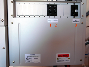
PDP DC area closed up with labels
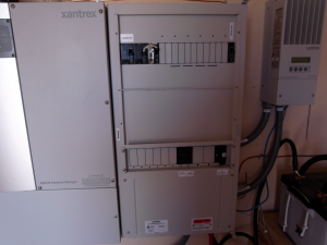
PDP closed up without its door
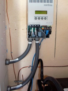
SCC wired and networked
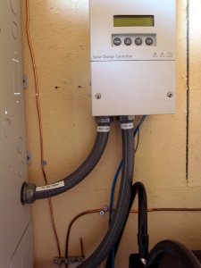
SCC wired and closed
At this point, we’ll trying hooking up something AC-powered and see how it goes.
I plan to have a couple of outlets inside the battery house. I also have fluorescent lighting to be installed. I will also install a couple of outlets outside near the front door to replace our trusty but tiring generator.

