xantrex

...now browsing by tag


Trouble on the solar horizon?

Thursday, July 7th, 2011

Our system has been running for a year and a half now without a single outage. I did finally order a generator. It’s not here yet, but it’s on its way. I was waiting for a reason to place the order; hoping not to cut the purchase too close – still hoping that. So, what prompted me to place the order? It was the second day ever that we failed to fully charge our battery bank.

The first day the batteries didn’t charge was not a surprise. It was a very cloudy day and the clouds started early. The second time was clear as a bell; there was not a cloud in sight. Hmmm. That’s odd. And a little scary to me. It’s summer. We’re are seeing some solar power production for 11 hours a day. The sweet spot is still before and after noon as always. How could this be?

I posted on a couple of forums that discuss solar power related topics asking what might cause this and got a lot of responses.  Many were useful, some were not. One that said to ignore the problem unless I actually run out of power I marked as not useful despite his being something called a super-moderator. Most people suggested different things that might cause this loss in power: lose or broken wiring, bad solar panels, faulty solar charging unit, poor alignment to the sun, dust in the air and dirt on the panels.

Before I get on to the debugging section, a bit about the problems debugging the system. Well- it’s a system. There are many parts from different companies. Everything they do is somehow tied together. If there were a problem with the batteries it could cause this problem. The solar charging controller uses all available power when bulk charging, but uses less as the batteries get full. This looks like the panels are producing less power, but it’s actually less being used.

I started at what seemed like the beginning to me. I tighten everything that could be tightened. I took apart every cover and found them all. That didn’t help. I washed the panels in plain water with a mop. I realigned the panels to the sun. It was a tiny change and didn’t seem worthwhile, but I would do anything to track this down.

At this point I was feeling like I had looked at everything that I might be responsible for. It was time to consider that the solar panels are bad or the solar charging unit is bad. (The solar charging unit was the least likely to me.) Maybe something really strange like one of the DC breakers was bad.

I did a close inspection of the solar panels and saw nothing interesting or odd. The description I heard from someone with bad panels was that the damage was obvious.

Next I started to test the panels as best I could. Each group of three panels are wired together (in series) and it’s not easy to test them individually. Still, I figured that testing each group would reveal something interesting. I mean, it’s unlikely that more than a few panels would be bad. This means one or two of the groups should show reduced power compared to the rest. I carefully turned off and on each breaker; measuring the power before and when it breaker was off. When I was done every group tested just the same. I tried this again except that this time I turned all the breakers off and then turned each one on and the off. Still no difference. The panels seem fine. Well that, or they are all equally bad.

Somewhere around this point in the debugging it hit me that it’s been really hot lately-much hotter than last year. I started to wonder if heat was playing a factor in this. A few people responded in the forums that high heat did reduce the effectiveness of solar panels.

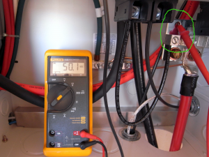
I contacted Kyocera via email to ask about the problem. They were very helpful. And not just helpful, but they did not prejudge the situation or suggest they were not responsible. They asked me to test a few things. None of the tests found anything very interesting. The amount of power being produced was down to 1900 watts versus 2880, the all time high. I mentioned the extreme heat here to the Kyocera representative and they did some calculations. They were guessing a surface temperature of 150 F degrees based on the outside temperature. At 150F you can expect about a 25 percent loss in power. Assuming the power the panels are rated at: 2520 watts for the 12 panels, a 25 percent loss would put you at 1890. I’m seeing  little better than that. More evidence that it’s the heat is that when I sprayed the panels with water from a hose the power output went up 200 watts in just a few minutes. And best of all was a cloudy day. The sun was behind the clouds for a good half-hour and then it returned strong. The panels had clearly cooled down because I saw 2500+ watts for awhile before it gradually began to drop.

So no, there is not trouble on the solar horizon. The only issue is that I had planned on having more power than I do. Still, this happens in summer and the days are longer. Plus, the generator is on its way. (Just got a call and it should be here tomorrow.) And frankly, I don’t think we’ve ever really taxed the batteries.

The battery voltage drops fast once the sun is down. Until it doesn’t that is. Then it goes slow. And I suspect, slower and slower and maybe slower than that. I’ve never been inclined to really test how long the batteries will last without sun. It seemed too dangerous as the sun would certainly not shine the next day if I ran it all the way down. Once the generator is up and running, it might be time to find out.

Installing a Xantrex XW – part 4

Monday, January 18th, 2010

Well, I started up the inverter today — it was uneventful; everything worked. We have AC power. The solar array charged the battery bank. It was the good kind of uneventful.

I threw the breaker labeled “Inverter Disconnect,” which connected the battery bank to the inverter. The inverter flashed for a second and then lit up showing the battery full. The System Control Panel turned on and showed a warning/fault. I looked at the warning, and it just let me know that new devices were added to the system.

I set the date and time and nothing else really.

Then I turned on the breaker adding the Solar Charge Controller (SCC) into the system. I immediately got another warning – Yes, a new device was added into the system. I did need to configure a couple of of things: battery type and the amp hours of the battery bank. It already knew the voltage of the battery bank.

Then I threw the last breaker to allow power from the solar array to the SCC. Almost immediately I saw voltage from the solar array displayed on the SCC. Soon the batteries were charging. The battery bank was about 50 volts when I began and about 54 volts by the time I left for the day.

And that’s it.

I think Xantrex (now called Schneider Electric or so I hear…) built a great system. Their manuals were great. The wiring diagrams were the best. I read all the manuals and studied the wiring diagrams and as far as I can tell everything worked. I am very happy.

We bought all our solar equipment from Northern Arizona Wind and Sun. I have to say that they were very helpful. They did several quotes for me as I tried to understand what it was I wanted. They did a wonderful job of making sure I bought all the things I needed and nothing I didn’t need. We got a big pile of stuff and it’s all somewhere doing something. While I was doing the installation, I frequently emailed them questions or requests for advice — again, they were very helpful and cheerful about helping. And, their prices were good… very good.

Here are some pictures:

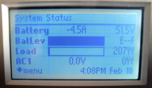
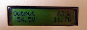
SCC display of the power from the solar array

SCC display of the power from the solar array

The inverter display

The inverter display

The inverter status on the SCP

The inverter status on the SCP

Displaying the SCC info in the SCP

Displaying the SCC info in the SCP

Running a 500 watt light to test a load

Running a 500 watt light to with test a load

-fin-

Installing a Xantrex XW – part 3

Sunday, January 17th, 2010

It’s been a little while since I worked on the Xantrex (solar) system. Two main things caused the delay. One was that a few items needed to be ordered before I could finish the installation. The other was that we got started with the first coat of stucco and wanted to finish that as quickly as possible.

What needed to be ordered? We needed two DC breakers and one AC breaker. The DC breakers are clearly called for in the wiring diagrams. I wondered why they didn’t just come with the inverter. I can only assume that it’s because there are so many possible ways to configure this system and that some don’t use those breakers. The AC breaker is because I want power in the battery house. Other things I needed were flexible conduit, 3/4 inch and 1/2 inch, adapters for the 1 inch knockouts to 3/4 and 1/2 inch.

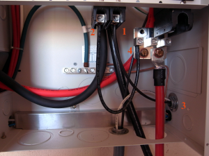
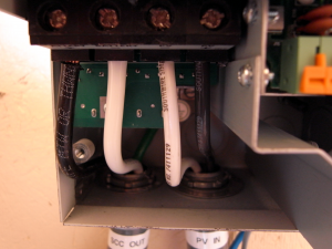
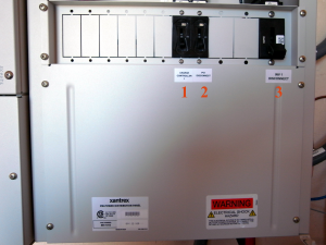
The first thing I tackled was the wiring of the solar array to the SCC. I used one of the new DC breakers to do this. The negative wire coming from the solar array goes into the PDP and directly to the PV- spot in the SCC (the white wire at #3 below). The positive wire goes to the top of the new DC breaker (the top of #1 – not visible). A new wire is added from the bottom of this breaker to the PV+ in the SCC (See #1 goes to #3). Note that this was done with the breaker in the OFF position.

PDP DC wiring

PDP DC wiring

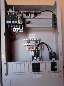
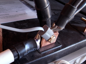
I then ran the wires from the SCC to the battery. These wires allow the SCC to charge the battery bank. The negative wire from the SCC goes to the DC negative busbar in the PDP (See the white wire above #2 below). The positive wire goes to the top second new DC breaker (also in the off position). (See #1 below.) A new wire goes from the bottom of this breaker to the positive DC busbar (See #2 and #4 above) attached to the large DC breaker where the positive cable from the battery attaches.

The upper half of the PDP

The upper half of the PDP

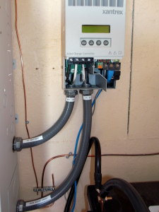
Solar Charge Controller wiring

Solar Charge Controller wiring

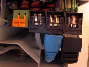
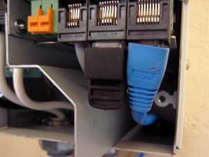
Next the networking cables needed to be attached and then moved. For whatever reason, I placed the network terminator to the right. When I went to install the cover for the SCC, it would not fit because the terminator blocked the place where the screw attaches. I reversed the cable and the terminator, and all was well.

Networking and battery sensor cables

Networking and battery sensor cables

Adjusted so the cover fits

Adjusted so the cover fits

The battery temperature sensor was attached in the SCC as well. Speaking of the battery sensor… I’ve read the manuals quite a bit and was not sure what to do with the two battery sensors I received. Somewhere I read that only one was required; the data is shared on the network. Elsewhere I read that if there is more than one, whichever  one has the higher value is used. That made me think that there’s value in using both of them. So I installed both of them. One attaches to the inverter and the other to the SCC. I attached the sensor ends to two different batteries in the battery bank.

The battery sensor installed

The battery sensor installed

The next thing I did was to hook up the positive cable from the battery bank. The only tricky thing about this is that it made sense to me to connect the cable inside the PDP first and then connect the other end to the battery bank. I was worried about touching the hot end of the cable somewhere inside the PDP it should not touch.

I believe the system is ready to be turned on. I decided to give it a day before doing this. I’ve read over the manuals and think I’m ready. I’ll turn on the system tomorrow.

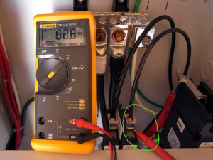
Voltage from the battery bank at the PDP

Voltage from the battery bank at the PDP

Solar array voltage at the PDP

Solar array voltage at the PDP

The order of operations as I see them is to first throw the breaker (#3 below) that connects the battery bank. This should bring up everything except the SCC. There may be a little bit of configuration required at this point. It seems that everything can be done from the System Control Panel. I believe the SCC can be configured at this point, but I’m not positive. At this point, the system should be inverting; it should be just like there is battery power, but nothing is coming from the solar array.

If all goes well, I will next throw the breaker (#1 below) that connects the SCC to the battery. If I need to do additional configuration, I’ll do it at this time. I think I need to enter the battery type (AGM), the amp hours of the battery bank (1530) and  possibly the voltage of the battery bank (48). I read that it will determine the battery bank voltage itself, but I also read that I will need to enter it. I guess we will see.

Again, assuming all is well, I will throw the last breaker (#2) which will allow power from the solar array to reach the SCC.

PDP DC area closed up with labels

PDP DC area closed up with labels

PDP closed up without its door

PDP closed up without its door

SCC wired and networked

SCC wired and networked

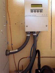
SCC wired and closed

SCC wired and closed

At this point, we’ll trying hooking up something AC-powered and see how it goes.

I plan to have a couple of outlets inside the battery house. I also have fluorescent lighting to be installed. I will also install a couple of outlets outside near the front door to replace our trusty but tiring generator.

Installing a Xantrex XW – part 2

Wednesday, December 30th, 2009

Today we mounted various components and started wiring things together. I’m afraid this will jump around a little. (And please if any one notices me doing anything suspicious, speak up.) First thing today, I connected the thick cables that will bring power from the batteries to the inverter. There is one really large breaker/disconnect between the batteries and where they connect to the inverter here. Note that I still have not connected the batteries to the system.

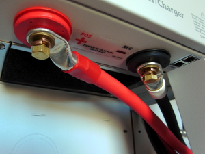
The heavy cables that bring power from the batteries

The heavy cables that bring power from the batteries

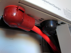
Xantrex provides covers for the power connectors

Xantrex provides nice covers for the cables

Next I mounted the other of the parts of the system: System Control Panel, Automatic Generator Start, and the Solar Charge Controller. My continuing education made a jump today when I realized why there are two battery chargers in the system. The one in the inverter converts AC from the generator, (or the grid if you have such a thing) the Solar Charge Controller converts DC from the Solar Panel array for battery charging. (It’s smarter than that actually (see MPPT), but basically that is it.)

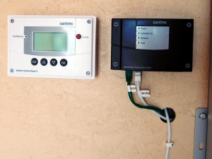
SCP and the AGS

SCP and the AGS

And, yes that is a giant heat sync built into the SCC.

Solar Charge Controller (MPPT)

Solar Charge Controller (MPPT)

You will see what look like network cables running between the different component. And, indeed they are good old CAT5 network cables. All the devices talk to each other. There’s something a little funky in the system given that each device has two network connectors and the two ends have special terminators. It seems odd to me, but I assume they are doing interesting things. (One thing that I am sure of, is that they are providing power to some of the devices.) Here’s a picture of everything mounted. The installation instructions tell you to run the network cables early because things get crowded later on. I took them at their word and ran the cables as soon as the everything was mounted.

Xantrex XW system with accesories

Xantrex XW system with accesories

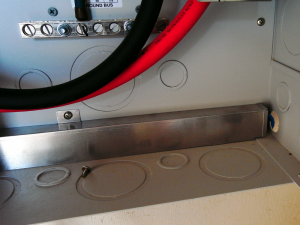
The next three pictures show the paths the network cabling take. Inside the PDP, there are special raceways for the network cabling. This is to shield the cables from interference and to help keep things organized.

From the SCC to the inverter

From the SCC to the inverter

From the inverter to SCC and the AGS

From the inverter to SCC and the AGS

SCP and the AGS

SCP and the AGS

You don’t see cabling to the SCP because it’s in the wall. For some reason, the SCP mounting hardware really wants a hole in the wall for the network cable; I obliged.

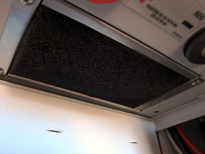
Now that I remember, the very first thing I did was install the air filter in the bottom of the inverter. You just push it in place with your hands.

The air filter

The air filter

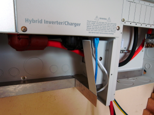
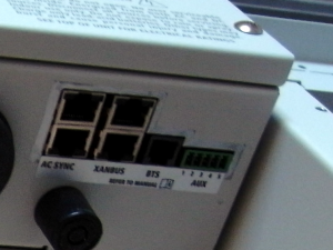
Close up of the inverter connections

Close up of the inverter connections

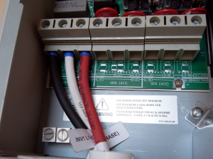
The last thing for today was to connect up the wires that bring AC from the inverter to the breakers from which the house is the next stop.

AC out from the inverter

AC out from the inverter

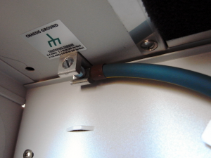
And to ground the inverter.

The ground lug in the bottom of the inverter

The ground lug in the bottom of the inverter

Installing a Xantrex XW – part 1

Tuesday, December 29th, 2009

We are completely off grid. Our Xantrex system comprises an inverter, a battery bank, and a solar array.

We got the Xantrex XW6048 inverter as the brains/workhorse of our solar-powered system. Part of the reason for going with this system (rather than pieces) is the same reason I wanted the guy doing our concrete slab also taking care of the plumbing in the slab–I don’t want any finger pointing. Also, Xantrex has a great reputation. I think everyone around here that I have visited (on my tour of places using solar power) had a Xantrex inverter and they all seemed quite happy.

I searched the web for “Installing a Xantrex XW” and found nothing – nothing useful. I hope this will help others as I seem on my own… as far as the internet goes anyway. P.D. has been enormously helpful and I’m developing a small group of great people to ask questions of via email.

Xantrex gives you really great documentation. There’s a big bound manual and a color fold-out diagram/layout that shows many possible configurations-grid tied, off-grid, single or multiple inverters, etc. It all seems a bit over my head, but I think I can work through it.

As for the rest of the system, we got the Control Panel, which lets you configure and monitor all the different parts of the system from one panel, the  Power Distribution Panel, the Solar Charge Controller, and the Automatic Generator Start. I’m sure we will need some additional parts to get it running, but was a ready to begin.

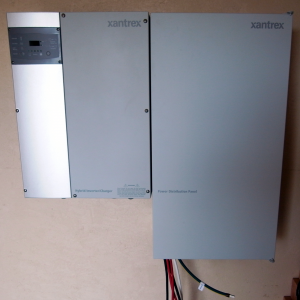
The first matter at hand is mounting the equipment. The inverter weighs something like a hundred-thirty pounds. You don’t want to fool around with this. They give you a really solid mounting plate for both the inverter and the Power Distribution Panel (hence forth know as the, PDP).

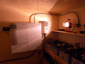
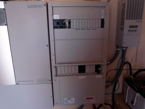
The Inverter and the PDP mounted

The Inverter and the PDP mounted